Benefits of Thorium ?
Known and experimented since the 50s, thorium has the following advantages:
- Waste: Waste produced by thorium nuclear plants are much reduced and have a much shorter lifetime than its uranium 235 counterpart. There is no need to store them for periods extending over thousands of generations.
- Security: In this field, thorium is a class apart. The many safety devices are of passive type and work on the laws of physics without any technical or human intervention. Thorium systems function at ambient pressure, and the rubbiatron, for example, shuts down by itself in case of system failure or earthquake. This is due to its characteristic subcritical reactor. The waste heat is then continuously removed by natural convection, without further consequences.
- Efficiency: Almost all of the thorium can be converted into thermal energy (against only 1/200 in the case of uranium). This diminishes the amount of waste and lost energy.
- Abundance: Thorium is nearly 4 times more common in the crust than uranium (9.6 mg / kg against 2.7 for uranium). Considering its efficiency, it means that the thorium can ensure a future energy production 700 times longer than uranium.
- Nuclear Proliferation: The thorium and its by-products have excellent resistance characteristics to nuclear proliferation. The militarization of this sector requires too complex processes to be useful and thorium produces only trace amounts, in practice unusable, of plutonium. This is an obvious advantage.
- Flexibility: It is very possible to build thorium plants that can easily and quickly adapt to irregular production of renewable energy, which the U systems do not allow.
- Bonus: On top of that, some thorium systems allow for the transformation -with energy production-of the U-generated highly radioactive waste into manageable waste with a shorter lifespan. This is probably the best (only) way to solve the problem of nuclear waste created during almost 40 years.
So why not earlier?
- On the one hand for economic reasons (U precedence in research) and partly because this sector was not useful to nuclear weapons. And perhaps for lack of specialists busy with uranium systems.
The ITHEC think it is time to correct the wrong choice due to the cold war and quickly convince civil society that “nuclear power” does not mean “uranium-235″To quickly build thorium “waste-eaters” plants before we lose control over nuclear waste andSet up additional energy production systems complementary to renewable energies (adjustable continuous production).We are about to enter a new nuclear era!
WHAT IS THE ENERGY AMPLIFIER ?
The Energy Amplifier (EA) is the result of a “cross-fertilisation” between the technology of modern accelerators, as for instance pursued at CERN and the one of Nuclear Power and in particular the development of fast neutron breeders and of the fuel reprocessing (MOX). In contrast with an ordinary reactor, in the EA energy in form of heat is produced as the result of nuclear cascades, rather than of a self supported chain reaction. Nuclear cascades are initiated by relativistic protons produced by a small but efficient accelerator. Like in the case of Fusion the produced power is directly proportional to the intensity of such an injected beam, which is intrinsically limited by the structure of the accelerator. The basic physics and the conceptual design of the EA are comprehensively illustrated in the paper CERN/AT/95-44 (ET)[1]. The underlying physical principles of “Energy Amplification” have been demonstrated in a recent experiment performed at CERN[2].
There is no doubt that environmental and safety features will govern any new development in the field of energy from nuclei. The reference level of radio-toxicity of the “waste” should be lowered to the one of the ashes from Coal burning, where tiny amounts of radio-nuclides of the U and Th decay chains are present and which is an obvious case where in contrast with Nuclear Reactors the Geological Repository is not required.
The EA has safety and environmental advantages which are comparable to the ones of the “state of the art” Magnetically Confined Fusion, as it is described in the comprehensive Report of the Safety and Environmental Assessment of Fusion Power (SEAFP) undertaken for the DG XII[3]. While the development of an Energy Amplifier represents a relatively modest extrapolation of technologies of today’s accelerators and nuclear energy and therefore can be relatively well predicted, the assessment of future fusion power plants requires extrapolation from present day physics and technology to a time many decades ahead. It requires in particular judgements as to feasibility in the areas of plasma confinement, stability, exhaust and special materials.
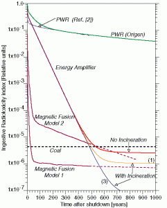
(a) Ordinary PWR reactor.
(b) Models 1 and 2 of MF from J. Raeder et al.
(c) Predictions of EA without FFs incineration and two levels of incineration as discussed in CERN/AT/95-58 (ET)
(d) the ingestive radiotoxicity produced by a coal-fired plant due to impurities in Coal, according to J. Raeder et al. Coal burning associated, long lived radiotoxicity is a good reference case for no need of Geologic Storage.
Notwithstanding Magnetic Fusion (MF) projected performances represent a precise term of reference and a gauge with which the validity of the Energy Amplifier (EA) concept should be evaluated. In both cases, after a suitable “cool-down” period, radioactive “waste” reaches radio-toxicities which are comparable and smaller than the one of the ashes coming from Coal burning for the same produced energy.
The cool-down time is in general shorter for MF, but in both cases it does not exceed about 500 years, after which period materials can be safely stored at a shallow depth (like in the case of Coal ashes). The volume of “waste” is much larger in the case of MF, which has the added presence of a large stockpile of Tritium which must be extracted and re-processed on-line. Both devices after such a reasonable cool-down period are enormously cleaner (5 x 10⁻⁵ for toxicity of waste after 500 years) than the present and future generations of (Pressurised Water Reactors) PWRs.
Both the EA and MF can be effectively protected against military diversions and exhibit an extreme robustness against any conceivable accident, always with benign consequences. In particular the [beta]-decay heat is comparable in both cases and such that it can be passively dissipated in the environment, thus eliminating the risks of “melt-down”. The much simpler structure, the excellent heat distribution over the volume ensured by the natural convection of the molten Lead, the much smaller number of components and the smaller unit power of the EA (1.5 vs. 3.8 GW) are added advantages and in general ensure an even better safety margin.
Both MF and EA satisfy the safety related “central points” as defined by the European Fusion Programme Evaluation Board[4] (Colombo Committee) namely:
(1)”It must be clearly shown that the worst possible fusion accident will constitute no major hazard to populations outside the plant perimeter that might result in evacuation”
(2)”Radioactive wastes from the operation of a fusion plant should not require isolation from the environment for a geological time span and therefore should not constitute a burden for future generations”
The natural abundances of the materials used as fuel by MF and EA (Lithium and Thorium, respectively) offer roughly the same energetic potentials: they are sufficient for millions of years of very intensive utilisation. A reasonable extrapolation [CERN/AT/95-44 (ET)] of the Thorium ores with a metal content larger than 2000 ppm, the presently exploited Uranium level, indicates energetic reserves corresponding to 2200 centuries at twice the present world’s consumption, truly unlimited on the scale of human civilisation. For such a very long timescale a distinction between renewable and non-renewable energies is in both cases merely academical.
HOW DOES IT WORK ?
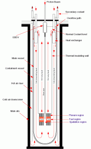
The EA design is the one described in CERN/AT/95-44 (ET) and it is shown in Figure 2. It is based on a convection driven molten Pb swimming pool roughly of the mass required for the eutectic Lil7Pb83 breeder/multiplier of Model 2 (~104 tons) for Magnetic Fusion described by J. Raeder et al. The choice of fast rather than thermal neutrons is motivated by the higher attainable power density and the larger burning efficiency for the higher Actinides. For more details we refer to CERN/AT/95-44 (ET). The nominal thermal power has been set to 1500 MW. Several modules could be clustered in a power installation. The coolant medium is molten natural Lead operated in analogy with Fast Breeders (Sodium cooled) “models” at a maximum temperature of 600 / 700 oC. In view of the high boiling temperature of Lead (1743 oC at n.p.t.) and the negative void coefficient of the EA, even higher temperatures may be considered, provided the fuel and the rest of the hardware are adequately designed.
A most relevant feature of our design is the possibility of using natural convection alone to remove all the heat produced inside the core. Convection cooling has been widely used in “swimming pool” reactors at small power levels. It has been shown in CERN/AT/95-44 (ET) that an extension of this very safe method to the very large power of the EA is possible because of the unique properties of Lead, namely high density, large dilatation coefficient and large heat capacity. Convection is spontaneously and inevitably driven by (any) temperature difference. Elimination of all pumps in the primary loop is an important simplification and a contribution towards safety, since unlike pumps, convection cannot fail. In the convective mode, a very large mass of liquid Lead (~ 10,000 tons), with an associated exceedingly large heat capacity[5] moves very slowly (<= 2.0 m/s inside the core, about 1/3 of such speed elsewhere) transferring the heat from the top of the core to the heat exchangers located some 20 metres above and returning at a lower temperature ([Delta]T ~ – 200 oC) from the heat exchangers to the bottom of the core.
There are four 375 MWth heat exchangers to transfer the heat from the primary Lead to the intermediate heat transport system. They are located above the core in an annular region between the support cylinder and the walls of the vessel.
The vessel is housed below floor level in an extraordinarily robust cylindrical silo geometry lined with thick concrete which acts also as ultimate container for the liquid Lead in case of the highly hypothetical rupture of the main vessel. In the space between the main vessel and the concrete wall the Reactor Vessel Air Cooling System (RVACS) is inserted. This system, largely inspired from the ALMR design, is completely passive and based on convection and radiation heat transfer. In case of a thermal overheating, the significant dilatation of the molten Lead will raise the level of the liquid which (see Figure 2) activates (1) the RVACS cooling, (2) stops the proton beam by flooding an appropriate emergency beam stopper (EBDV) and (3) scrams the EA at a lower multiplication coefficient k <= 0.90. The whole vessel is supported at the top by anti-seismic absorbers. Even in the case of an intense earthquake the large mass of the EA will remain essentially still and the movement taken up by the absorbers.
The fuel is made of mixed oxides, for which considerable experience exists. More advanced designs have suggested the use of metallic fuels or of carbides. These fuels are obviously possible also for an EA. We remark that the use of Zirconium alloys is not recommended since irradiation leads to transmutations into the isotope 93Zr, which has a long half-life and which is impossible to incinerate without separating it isotopically from the bulk of the Zirconium metal. The choice of the chemical composition of the fuel is strongly related to the one of the fuel reprocessing method.
A relative novelty of our machine when compared to ordinary Pressurised Water Reactors (PWRs) is the large concentration of ThO2 in the fuel and the corresponding production of a small but relevant amount of Protactinium. A liquid separation method called THOREX has been developed and tested on small irradiated ThO2 fuel samples. The extrapolation from the widely used PUREX process to THOREX is rather straightforward and this is why it has been chosen [CERN/AT/95-44 (ET)] at least at this stage, as a “proof of existence”. Methods based on pyro-electric techniques are most interesting and probably the way to go, though they still require substantial research and development work.
Since the destination of the Actinides is now well defined i.e. to be finally burnt in the EA, the leakage of Actinides in the Fission Fragment stream must be more carefully controlled, since they are the only Actinides in the “Waste”. We have assumed that a “leaked” fraction of f = 10-4 is possible for Uranium. The recycled fuel has a significant radio-activity. We have checked that the dose at contact is similar to the one of MOX fuels made of Uranium and Plutonium, already used in the Nuclear Industry.
No scheduled intervention is therefore foreseen on the fuel during the five years of operation, at the end of which it is fully replaced and reprocessed. Likewise in the “all-convective” approach there are no moving parts which require maintenance or surveillance. In short the EA is a large, passive device in which a proton beam is dumped and the generated heat is extracted, without other major elements of variability.
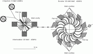
Normally the EA is well away from criticality at all times (0.95 <= k <= 0.98), there are no control bars (except the scram devices) and the power produced is directly controlled by the injected beam current. The accelerator is a synchronous cyclotron with an accelerated continuous current of 10 / 20 mA and kinetic energy of 1.0 GeV (Figure 3). It makes use of warm magnets (Bmax = 1.8 Tesla over 5 cm magnet gap) and RF-cavities. Experience with these machines has shown that the beam losses can be made sufficiently small so that no remote handling of the machine components is necessary. In particular the accelerator can be housed outside the containment region. The nominal external power provided by the beam is Pext = 12.5 MW, corresponding to a gain G = PEA/Pext= 120 (to be compared with G = 40 for MF).
Therefore in the case of the EA the external power source is about 1/3 of the one assumed for MF for a given power production[7]. The heat flux extracted by the Lead coolant from the fuel pins is on the average 100 W/cm2 = 1 MW/m2, a factor 2 / 3 larger than the one of the first wall of MF[8]. The peak power density in the beam window is of comparable magnitude, namely 113 W/cm2 = 1.13 MW/m2, but much smaller than the one of the divertor of MF (5.0 / 10 MW/m2).
Both conceptual designs are to be intended as reference models and many variations are possible. It should be emphasised that there are many other possible choices both for MF and EA. In the case of MF a number of working hypothesis have been introduced by CERN/AT/95-44 (ET) in order to bridge the present gaps of knowledge.
WHY AN ENERGY AMPLIFIER ?
In my view, the EA deserves consideration as a serious candidate for low cost, clean Nuclear Energy in the foreseeable future, and this for the following main reasons:
(1) The technology is mature and an EA can be constructed sensibly and quickly within the present state of the art. There are precisely three specific and well defined components which must be realised with a reasonable extrapolation of present technologies, namely:
(i) The Accelerator
(ii) Energy producing tank
(iii) Fuel fabrication and reprocessing .
(2) The EA may fulfil the main new missions of Fusion with respect to ordinary Nuclear Energy, namely:
(i) Elimination of the Geologic Storage (“waste” less radioactive than coal ashes after a reasonable cool-down period);
(ii) Elimination of the “Criticality” and “Melt-down” accidents;
(iii) A better use of primary element for the fuel which is burnt at the theoretical efficiency, namely ~200 times more effectively than PWR (the never fulfilled goal of Fast Breeders);
(iv) It permits the use of Thorium and therefore the development of a Plutonium-less nuclear energy.
(3) The EA can be a natural, cheaper and safer substitute for present electricity producing nuclear energy at the end of the now operating reactor lifetime and for new installations in the developing countries. Timing in this respect seems for EA better than for MF; 10 years from now to the demonstration plant and 20 years to the massive utilisation brings the timing of EAs in synchronisation with the end of the presently operating Reactors. Neither Fusion nor renewable energies will be ready on time to replace the amount of power produced by the present generation of Reactors (6% of the world consumption). Replacement of nuclear with fossil fuels will represent a serious increase of the Carbon Dioxide emissions. Incidentally we remark that the new generation of thermal PWRs, although they introduce significant improvements on the questions of safety (better containment and cooling of decay heat), they leave the problems of the long lived waste and of the Geological Repository untouched. In particular they keep producing vast quantities of Plutonium which nobody wants and which represents a considerable risk.
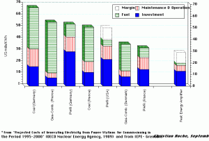
(5) Any new energy source must be cost competitive with standard fossil sources, namely Oil, Natural Gas and Coal. The present energy figures for high quality heat[9] are of the order of 4 / 5 $/GJ from Natural Gas and 3 / 4 $/GJ from Coal. No major changes are expected in the foreseeable future. The energy cost from the EA has been estimated to a first order and found significantly lower than conventional sources, namely about 1 / 2 $/GJ. This price edge ensures for instance that synthetic production of substitutions to fossil fuels, like synthetic Hydrogen from water splitting are economically possible [CERN/AT/95-12 (ET) (1995)]. The concept due to Marchetti of a concentrated cluster of nuclear energy producing units with Hydrogen as intermediary medium has many positive features:
(i) major cost reductions due to standardisation of units and centralisation of the overheads
(ii) added safety when compared to a distributed system of nuclear power generators
(iii) high level of security since sensitive materials are concentrated in a small area for which an appropriate surveillance can be exercised
(iv) Practical possibility of using “in situ” a fraction of the neutron flux to incinerate the most pernicious elements of the nuclear discharge
(v) Hydrogen as substitute to natural Gas permits to multiply the uses of nuclear energy, including the one of producing electricity with local plants at the acceptable added overhead of chemical hydrogen generation.
(6) The EA can be used to eliminate effectively the military grade Plutonium from the stockpile of bomb-grade Plutonium from Military Arsenals [CERN/AT/95-53 (ET), December 1995]. The amount which needs to be eliminated is about 100 tons (>20,000 warheads), out of a total of about 300 tons, of which about 180 tons still in warheads. The political importance and the contribution to the security of Europe subsequent to the definitive elimination of this major liability of the Cold War does not need to be emphasised. The energy stored in 100 tons of military Plutonium is very large (it corresponds to 1400 millions of barrels of oil). It can be left as explosive energy or may be quietly burnt away in the EAs, transforming something nobody wants into a useful economic asset.
(7) the European Union (Norway included) consumes 18% of the primary energy supplies, but it has only 7% of proven coal reserves, 2% of proven oil reserves and 5% of proven natural gas reserves. According to the World Energy Council, by 2020 Europe’s reserves will have declined to a point at which only Norway is expected to have significant natural gas and Europe may well enter in a phase of rising dependence on imports. There are additional concerns which would be foolish to overlook, namely environmental pollution and the carbon dioxide emissions. The timely development of a “Fusion like” type of nuclear energy like the one offered by the EA may be of considerable strategic importance for Europe.
(8) According to the World Energy Council, huge financial resources will be needed for investment in the energy domain — cumulatively perhaps US-$ 30 trillions( 1012) for the next thirty years, which compare with the global GDP in 1989 of US-$ 20 trillions. In order to ensure to the European industry the largest part of this market we must also develop competitive methods of energy production: the EA will exploit the know-how in the fields of nuclear and of particle accelerators in which Europe has many points of strength.
WHEN AND HOW ?
The phase of conceptual design is now more or less completed as indicated by the enclosed documentation. Let me give some indication of the possible next steps. The next phase should be the one of a detailed design by an international collaboration which is shaping up already, of the main two components of the device, namely the accelerator and the energy producing tank. I expect that this phase might take of the order of 1-2 years and require approximately 20 M ECU. At this point we should be ready to construct a demonstration module. In analogy with the phase DEMO for fusion or of Phoenix for fast breeders, the machine should be able to produce in a sustained manner a substantial amount (several hundred Megawatts) of power to the grid. In this phase the machine might total a cost of the order of 300/400 M ECU, without conventional facilities to produce electricity, which should pay for themselves. The construction time could be of about five years. Since the conception of the EA is modular, this exercise will bring us a long way toward the commercial series, (for instance the accelerator will be essentially the same and the tank rather similar).
The innovative proton accelerator, in addition to the function of demonstrating large scale energy production has considerable additional scientific research potentialities. For instance it permits to realise a high intensity “spallation neutron source” for which there is growing interest in Europe.
FURTHER READING MATERIAL
(1)For a complete description of the principle of operation and theory of the EA we suggest:
C. Rubbia et al, “Conceptual Design of a Fast Neutron Operated High Power Energy Amplifier”, CERN/AT/95-44 (ET), 29th September 1995. See also C. Rubbia, “A High Gain Energy Amplifier Operated with Fast Neutrons”, AIP Conference Proceedings 346, International Conference on Accelerator-Driven Transmutation Technologies and Applications, Las Vegas, July 1994.
(2) For the experimental tests of the validity of the Energy Amplification concept:
S. Andriamonje et al., Physics Letters B 348 (1995) 697-709.
(3) For the EA as Plutonium incinerator, both for PWRs and surplus military Plutonium:
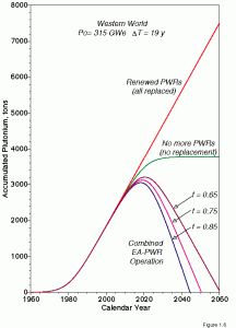
C. Rubbia et al. “A realistic Plutonium elimination scheme with fast Energy Amplifiers and Thorium-Plutonium fuel. CERN/AT/95-53 (ET)
C. Bowman et al., Nucl. Instr. and Methods, A330, 336 (1992).
(4) For comparison between the EA and the expectations of Magnetic Fusion:
C. Rubbia, A comparison of the Safety and Environmental Advantages of the Energy Amplifier and of Magnetic Confinement Fusion, CERN/AT/95-58 (ET).
(5)For EAs applicability to synthetic Hydrogen production:
C. Marchetti “The secular Dynamics of the Energy Systems”, 2nd International Conference on Energy Environment and Technological Innovation, Rome, October 1992.
C. Rubbia, “On the Feasibility of Fission Driven Hydrogen Production as Substitute for Natural Gas”, CERN/AT/95-12 (ET) (1995).
I.T. Öztürk, A Hammache and E. Bilgen, Trans. IChemE, 241, 72A, (1994).
(6) For a preliminary cost estimate, we suggest:
C. Roche and C. Rubbia, “Some Preliminary Considerations on the Economical Issues of the Energy Amplifier”, CERN/AT/95-45 (ET), 29th October 1995.
(7) For the environmental impact of Magnetic Fusion:
J. Raeder et al. “Safety and Environmental Assessment of Fusion Power (SEAFP)”, EUR-FU-BRU XII-217/95, June 1995.
[1] C. Rubbia et al, “Conceptual Design of a Fast Neutron Operated High Power Energy Amplifier”, CERN/AT/95-44 (ET), 29th September 1995. See also C. Rubbia, “A High Gain Energy Amplifier Operated with Fast Neutrons”, AIP Conference Proceedings 346, International Conference on Accelerator-Driven Transmutation Technologies and Applications, Las Vegas, July 1994.
[2] S. Andriamonje et al., Physics Letters B 348 (1995) 697-709.
[3] J. Raeder et al. “Safety and Environmental Assessment of Fusion Power (SEAFP)”, EUR-FU-BRU XII-217/95, June 1995.
[4] U. Colombo et al.: “Evaluation of the Community Fusion Programme
[1984-1990]”, Research evaluation – Report No. 45, EUR 13104 EN, July 1990.
[5] The heat capacity of liquid Lead at constant pressure is about 0.14 Joule/gram/oC. For an effective mass of ~ 104 tons = 1010 grams and a power of 1.5 GWatt ( full EA power), the temperature rise is of the order of 1.0 oC/s. The mass flowing through the core for [Delta]T ~ 200 oC is 53.6 tons/sec, corresponding to some 1.5 minutes of full power to heat up the half of the coolant in the “cold” loop, in case the heat exchangers were to fail completely.
[6] This choice is motivated by the relative novelty of the “all-convective” approach and the relative scarce experience with ThO2 , when compared with UO2.
[7] The indicated powers are the ones actually given respectively to the plasma or to the spallation source. The transformation of electric power (mains) to neutral beam or radio-frequency heating for MF have expected efficiencies (30 /50%) which are rather close to the one of our accelerator (43%). Hence the factor 3 in favour of the EA vs. the MF is also roughly valid if one compares the recirculated fractions of produced electrical energy.
[8] It is of course much easier to cool the pins immersed inside the molten lead than the first wall of MF facing the burning plasma. Note that the power density for the EA fuel is about 1/2 of the one in operation with Superphenix and MONJOU.
[9] “Energy in Europe, A view to the future”, DG XVII, special issue, September 1992
Why Thorium ?
- Using Thorium fission instead of Uranium reduces the toxicity and longevity of nuclear waste
- Thorium can be mixed with radioactive waste from current uranium-fuelled reactors inside new Thorium reactors to reduce the existing stockpile of nuclear waste.
- The waste products from a Thorium-fuelled reactor do not include weapons-grade materials in the amounts required for producing a bomb
- Thorium lends itself to its use in a sub-critical reactor, which operates far from criticality and is inherently safer.
- The decay heat which needs to be cooled after a nuclear reactor is shut down, can be removed passively in a Thorium ADS reactor.
- Thorium can be extracted from many parts of the globe, in less politically sensitive regions and in greater quantities than uranium
iThEC is an organisation placed under the patronage of Carlo Rubbia bringing together
- Scientific and technical knowledge from the world’s leading research institutes
- Political decision makers
- Industrial partnerships


